Introduction:
Ground control points (GCPs) are markers with known coordinates used in aerial imaging. Ground control points are useful because their known coordinates can be used as a reference in order to accurately map large areas. Ground control points are often square shaped markers like the one shown below in figure 1. Ground control points need to be easily recognizable. They are often black and white, patterned, or made with other high contrast colors.
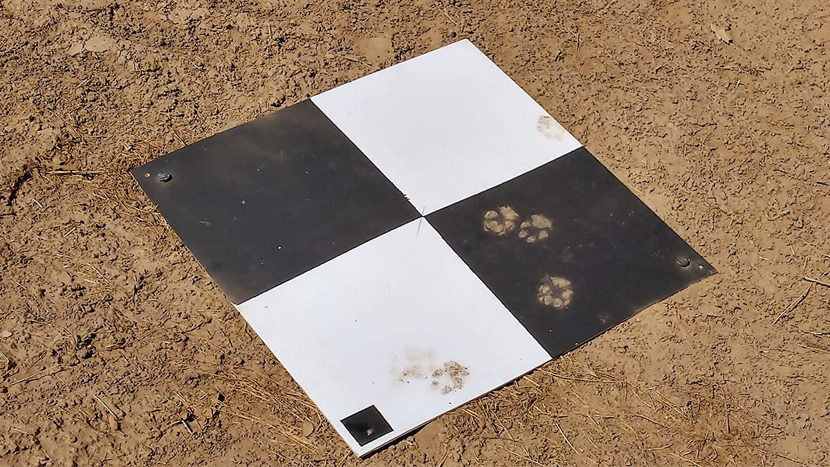
(Figure 1: GCP Example)
The purpose of this lab was to process the same imagery from lab 4, but this time ground control points are used in order to improve accuracy.
Methods Part 1: Importing the GCP Data
The first step in this process was to import the GCP data into pix4D. Once this is accomplished it is necessary to ensure that the output coordinate system and the coordinate system used for the ground control points are the same. Figure 2 below shows the selection of the appropriate coordinate system. The coordinate system used for this lab was the world geodetic system 1984. In order to correctly match the output coordinate system to the coordinate system used to collect the GCPs you can check the meta data. It is also necessary to make sure that the appropriate camera model is selected and the linear rolling shutter setting is selected. Figure 3 below shows the adjustment of the camera model settings.

(Figure 2: Matching Output Coordinate Systems to GCPs)

(Figure 3: Adjusting Camera Settings)
Methods Part 2: Processing the GCP Data
Once again the processing will be done in two separate parts. Initial processing is done separately from the generation of the point cloud and orthomosaic. Before this step it is important to make sure that certain settings regarding the GCP coordinates are correct. GCPs can be displayed in XYZ or YXZ format. In this case it is necessary to adjust the settings to YXZ. Figure 4 shows the adjustment of this setting. After slightly adjusting some more intial processing options initial processing can begin. After initial processing is complete a quality report is generated.

(Figure 4: Setting the correct coordinate order)
Methods Part 3: Marking and Optimizing
After initial processing is finished its necessary to make sure that the GCP's are as accurate as possible. This is accomplished by adjusting the location of a digital pointer/marker so that it lines up as close as possible to the center of the actual GCP. Figure 5 shows the overall process of correctly marking the GCPs. Figure 6 shows a close up of locating the actual GCP within the imagery. Figure 7 shows the difference between the GCPs before and after optimization. It is important to put the marker directly over the center of the angle. GCPs can be slightly more accurate when they are manufactured like the one in figure 1 above. However when making a temporary or painted GCP it is important to note that X shapes are often less accurate than L shapes. After the GCPs are marked steps 2 and 3 of the processing can be completed. The DSM and orthographic can then be generated.

(Figure 5: Optimizing GCPs)

(Figure 6: Setting the pointer over the center of the angle/ Locating the GCP within the imagery)

(Figure 7: Difference between GCPs before and after they are optimized)
Methods Part 4: Layout Maps and Comparisons:
Figure 8 Below shows a layout map made from data with GCPs. Figure 9 shows a layout map made from data without GCPs. As you can see there is a very significant difference in accuracy between the two. You can tell from the surrounding topography that the orthomoasic with GCPs is superior. An easy way to quickly realize this is to look at how out of place the pond near the top of the image is in figure 9. Figure 10 is an animation created using screenshots from arcGIS pro it was made by fading the two maps over one another in order to showcase the difference in the location with and without ground control points.

(Figure 8 Accurate GCPs Map)

(Figure 9 No GCPs)

(Figure 10 Maps overlaid with Transparency)
Conclusion:
Ground control points are necessary in order to create accurate maps using aerial imagery. They provide a reference point with known coordinates in order to align the imagery with a coordinate system. It is important to make sure that the coordinate system used to collect the GCPs is the same as the output before processing. After completing this lab I feel that I now have an understanding of how GCPs are placed, how their coordinates are recorded, and how they are used within software to create geographically accurate maps.